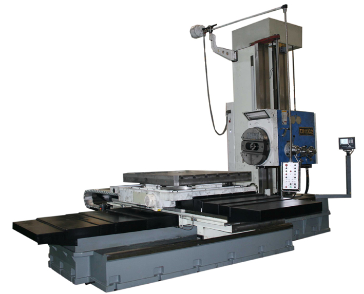
Features of TX6111C/2 TX6111C/3 DRO Horizontal Boring and Milling Machine
1. TX6111C/2 TX6111C/3 DRO Horizontal Boring and Milling Machine is of table-type layout, with column mounted on the bed and a side spindle head; guideway of the lower saddle is of cross structure.
2. A manual optical positioning device for at every 4x90° positioning of the table is provided for some models.
3. Some models positioned by a circular grating scale may make the table indexing continuously 360°;
4. Machine bed with larger specifications is added with integral auxiliary guideway;
5. Spindle system consists of three-layer structure, facing head spindle, hollow spindle and boring spindle;
6. The boring spindle is of high quality nitride steel 38CrMoAIA; the hollow spindle is of high quality alloy steel; the spindle is of high structure rigidity and accuracy;
7. The spindle with disk spring clamping and hydraulic unclamping makes tool handling easy;
8. Control system is provided with Mitsubishi PLC DRO unit and measuring elements are from SINO or NEWALL;
Applications of TX6111C/2 TX6111C/3 DRO Horizontal Boring and Milling Machine
Fortune Pacific TX6111C/2 TX6111C/3 DRO Horizontal Boring and Milling Machine are used for rough and fine boring and milling large-sized and medium-sized parts. Table is provided with an optical device for positioning at every 4x90° and can meet needs of in-line boring of parts with the table being turned for 180°. With integral inserted steel guideway, the structure rigidity of the machine is increased as a result. The spindle with disk spring clamping and hydraulic unclamping makes tool handling easy. Machine is provided with PLC, X and Y axes are provided with grating DRO unit, and reading accuracy is 0.005mm.
Technical parameters of TX6111C/2 TX6111C/3 DRO Horizontal Boring and Milling Machine
|
Main parameters |
Unit |
TX6111C/2 |
TX6111C/3 |
|
Spindle diameter |
mm (in) |
Φ110 (4.3’’) |
|
Spindle taper |
|
ISO 50 |
|
Spindle speed |
r/min |
18 steps; 9-1000 |
|
Main motor power |
kW |
7.5 |
|
Max drilling capacity of spindle |
mm (in) |
65 (2.6’’) |
|
Max boring capacity of spindle |
mm (in) |
300 (12’’) |
|
Speed of facing head |
r/min |
14 steps; 6-221 |
|
Travel of facing head slide |
mm (in) |
170 (6.7’’) |
|
Max boring capacity of facing head |
mm (in) |
600 (24’’) |
|
Table size (L x W) |
mm (in) |
1200x1100 (47’’x43’’) |
|
Max load of table |
kg |
4000 |
|
Transverse travel of table |
mm (in) |
1300 (51’’) |
1600 (63’’) |
|
Vertical travel of spindle head |
mm (in) |
1100 (43’’) |
1400 (55’’) |
|
Longitudinal travel of table |
mm (in) |
1400 (55’’) (equipped with end support) |
|
Axial travel of spindle |
mm (in) |
600 (24’’) |
|
Range of axes speed per spindle rotation |
mm/rev |
0.04-6 12steps |
|
DRO |
|
X, Y |
|
Overall dimension (L x W x H) |
mm (in) |
5200 x 3500 x 3300 (205’’x138’’x130’’) |
|
Net weight |
kg |
18300 |